-
TSCM 101 - DTV Signals Analysis
I have had a number of people let me know
that they appreciated the NTSC tutorial I put online, but have
been asking about DTV (or HDTV) and what the signal would look
like on a Spectrum Analyzer or OSCOR display.
Primer on Digital TV Signals:
The new Digital Television Formats utilize a different signal process providing a data stream as opposed to an analog video signal.
This permits a DTV (or HDTV) signal to carry far more signal information, and also permits small signal errors to be removed prior to display.
A DTV signal may be compared to a standard NTSC signal in a number of ways:
1) Signals will appear within the 6 MHz allocation of a normal NTSC signal
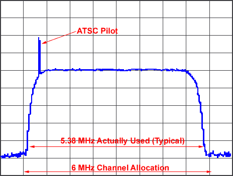
2) Instead of the Monochrome/Chroma/Audio signal (with three peaks) the DTV signal will show as a "6 MHz Raised Noise Floor"", with a spike or peak on the lower or left side of the waveform.
3) DTV signal will appear almost like a spread spectrum signal with a raised noise floor, but is actually a "pseudo spread spectrum" type of signal.
4) The DTV data signal is actually randomized in order to create a "flat noise like" spectrum common with digital signal transmission. This permits maximum channel efficiency and keeps the signal from interfering with nearby channels (so we can have three HDTV channels right next to each other).
5) The spike or peak on the lower side of the waveform is called the "ATSC Pilot" which provides one of three timing signals within the data stream.
6) The ATSC Pilot will consume about 7% of the total transmitted power, and will be smaller than a typical NTSC visual carrier (some simple math will provide a clue to how legitimate the signal is).

Notice that the bandwidth is roughly the same as a regular TV channel, and how the signal almost appears to be a spread spectrum signal. Also notice the ATSC carrier peak on the left side of the signal.
Simplified description of how the signal is created:
The MPEG circuit effectively takes a rasterized image, and transmits only what is changing or is different between video frames.
This digital data is converted into a high speed 19.39 Mbit/Second data stream that is created from an MPEG encoder circuit and provided to a DTV circuit (if it going to be broadcast via a TV channel).
The DTV circuit then takes this 19.39 Mbit signal adds framing information, and randomizes the data to "smooth" it out. Next the data stream is subjected to Reed-Solomon Encoding which breaks the stream into 207 byte packets.
Then signal is further broken up into Trellis Convolution Code which breaks the data up into four 2-bit words with built-in error correction.
A series of sync signals is then mixed with the data stream (Segment Sync, Field Sync, and ATSC Pilot) and the resulting signal applied to a 8-VSB modulator (or "8-Level - Vestigal Side Band") which provides the baseband signal.
The baseband signal is then mixed with a carrier signal to "up-convert" it to the desired channel or frequency.
This up-converted signal is typically 5.38 MHz wide and will show three distinct sync signals (the ATSC signal being the most obvious). The signal will normally be totally confined to within 90% of the 6 MHz channel allocation.
Keep in mind that MPEG is the same compression method used on your DVD player, and on DSS Satellite systems (do you see a trend here?).
Also remember that MPEG (and MPEG-like) video signals are fairly easy to create in an eavesdropping device. This eavesdropping signal may then be hidden inside of an already present DTV signal, or may be applied to a raw conductor.
There are already several companies who make compressed video/MPEG-like products for video eavesdropping which use the power lines or alarm circuits to conduct the signal back the listening post.
TSCM 101: "When performing radiated or conducted signals analysis; Beware of anything that appears to be any kind of an elevation in the -174 dBm noise floor"
Click HERE to obtain more TSCM Tutorials
| Home | What is TSCM | Types of Bugs | Warning Signs You're Bugged |
| How To Behave if Bugged | TSCM Threat Levels | How To Engage a TSCM Firm |
| Qualifications | TSCM Protocol | Bug Frequencies | Phone Taps and Bugging |
| Signal Analysis | TDR Analysis | TDR Tutorial | Wiretapping | Training | Tools |
| Equipment | OSC-5000 | Kaiser | Riser Bond | Avcom | Search Rcvrs |
| Outside Links | Recommended TSCM Books | TSCM Reference Library |
| Recommended U.S. TSCM Firms | TSCM-L Mailing List |
For a confidential consultation please E-mail: jmatk@tscm.com
-
Granite Island Group
127 Eastern Avenue #291
Gloucester, MA 01930
Telephone: (978) 381-9111
International Callers: 001-978-381-9111

